The Simulated Robot
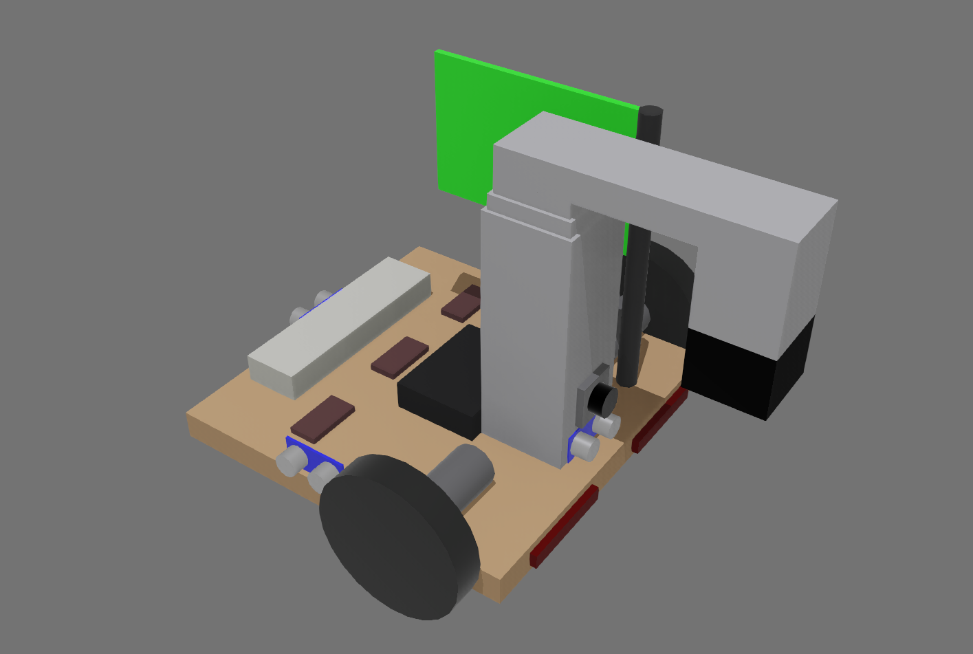
The simulator contains a pre-built robot model that can be controlled using the sr-robot3 library. The robot is a differential drive robot with a camera and a variety of sensors to sense its environment with. For the SR2025 competition, the robot has been equipped with a vacuum pump on on a lifting arm to pick up pallets.
Attached Boards
The robot has a number of boards attached to it that can be interacted with using the Robot API. These boards include:
- Power Board (serial number:
PWR)- OUT_H0 controls the vacuum pump. Enabling this allows the robot to pick up the pallets.
- Motor Board (serial number:
MOT)- The left wheel is connected to motor 0.
- The right wheel is connected to motor 1.
- Servo Board (serial number:
SERVO)- Servo 0 controls the lifter. Setting the position to -1 will move the lifter to the bottom position and a position of 1 will move the lifter to the top position.
- Arduino Board (serial number:
Arduino1)- The arduino has the SR Firmware installed. This firmware cannot be altered.
- The attached sensors are covered in the Sensors section.
- Camera (serial number:
Camera) - Brain Board - Including the LEDs that are attached to the Brain Board on the real robot (serial number:
LED)
Attached Sensors
All sensors are attached to the Arduino board and can be accessed using the Arduino API.
| Sensor | Connected Pin | Description |
|---|---|---|
| Front Ultrasound Sensor | Trigger: 2 Echo: 3 |
Measures distance from the front of the robot |
| Left Ultrasound Sensor | Trigger: 4 Echo: 5 |
Measures distance from the left of the robot |
| Right Ultrasound Sensor | Trigger: 6 Echo: 7 |
Measures distance from the right of the robot |
| Back Ultrasound Sensor | Trigger: 8 Echo: 9 |
Measures distance from the back of the robot |
| Front Left Microswitch | 10 | Detects if the front left of the robot has bumped into something |
| Front Right Microswitch | 11 | Detects if the front right of the robot has bumped into something |
| Rear Left Microswitch | 12 | Detects if the rear left of the robot has bumped into something |
| Rear Right Microswitch | 13 | Detects if the rear right of the robot has bumped into something |
| Left Reflectance Sensor | A0 | Measures the reflectance of the surface under the left side of the robot |
| Center Reflectance Sensor | A1 | Measures the reflectance of the surface under the center of the robot |
| Right Reflectance Sensor | A2 | Measures the reflectance of the surface under the right side of the robot |
Ultrasound Sensors
These are the simulated version of ultrasound sensors.
They return the distance to the nearest object in front of the sensor in a narrow cone of view. Objects beyond 4 meters are not detected.
The robot has four ultrasound sensors attached to it, one on each side of the robot. They can all be accessed using the Arduino API’s ultrasound interface.
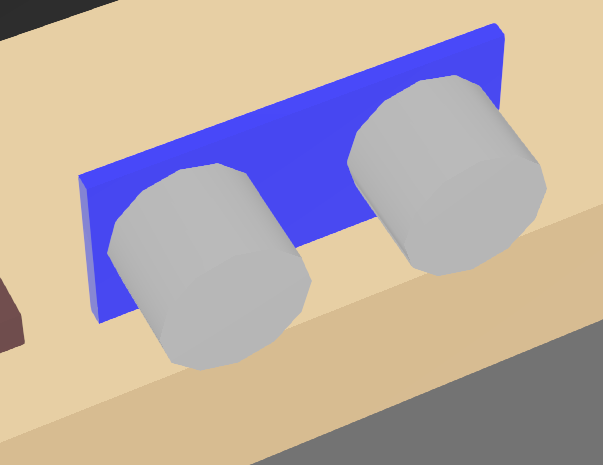
These appear as a blue board with two silver cylinders on the robot model. The returned distance is measured from the blue board in the direction of the silver cylinders.
Reflectance Sensors
Across the bottom of the robot, there are three reflectance sensors that can detect differences in the colour of the surface under the robot. This is achieved by returning the relative red content of the surface directly below the sensor.
The measured values can then be read using the Analog Input interface. This is returned as a voltage between 0 and 5 volts, with lower values indicating a darker surface.
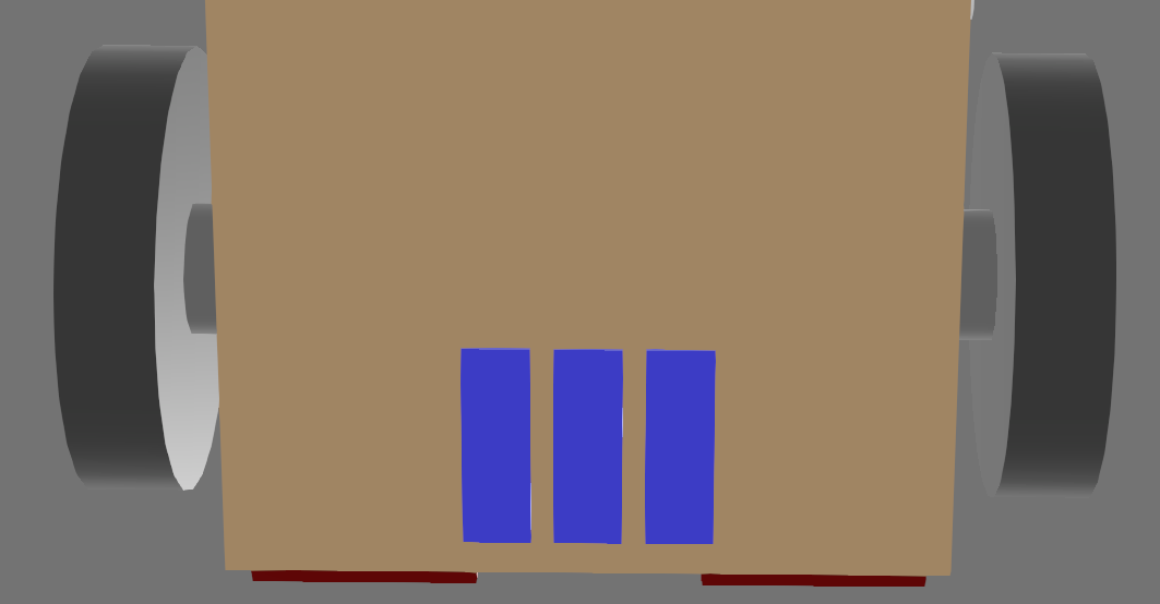
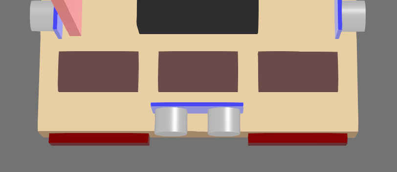
These appear as blue rectangles on the robot model.
Microswitches
On the front and back of the robot, there are microswitches that can detect if the robot has bumped into something. These appear as red cuboids on the robot model.
The attached pin will read True if the cuboid has intersected with any other object in the simulation.
LEDs
The three rectangles on the back of the robot can have their colours set using the Brain Board LED interface.